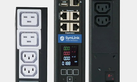
Switched PDUs for Intelligent Remote Power Control
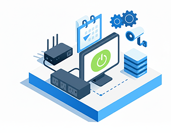
Switched PDUs provide outlet-level power control, automated device recovery, and remote management for IT racks, retail sites, AV systems, signage networks, and distributed environments.
Synaccess switched PDUs help teams monitor equipment health, reboot devices remotely, reduce on-site maintenance, and prevent downtime.
Synaccess switched PDUs help teams monitor equipment health, reboot devices remotely, reduce on-site maintenance, and prevent downtime.


.png)


.png)